TARGET LIQUIDS IN-FURROW
Restrictive Devices Explained
Restrictive Devices are designed to provide system back-pressure, essential to maintain accurate and even product distribution across the whole air drill or planter. There are two kinds of devices, Line Meters or Friction Tube.
Line Meters
Line Meters are a universal Restrictive Device suitable for Row Crop Planters and medium to high rate product application on Air Drills. Line Meters are strategically positioned within the “Terminal Assembly” of the “Stacker Distribution System”.
Location is critical. They must be located downstream from the 2 psi Check Valves to ensure that the Check Valves can function correctly. If line meter is positioned up stream, the check valves will constantly open and close (fibrillate), resulting in fractured streaming. To maximise efficiency and minimize lag time between shut-off and start-up at the terminal peripheries, the Line Meters should be located as close as is practicable to the opener.
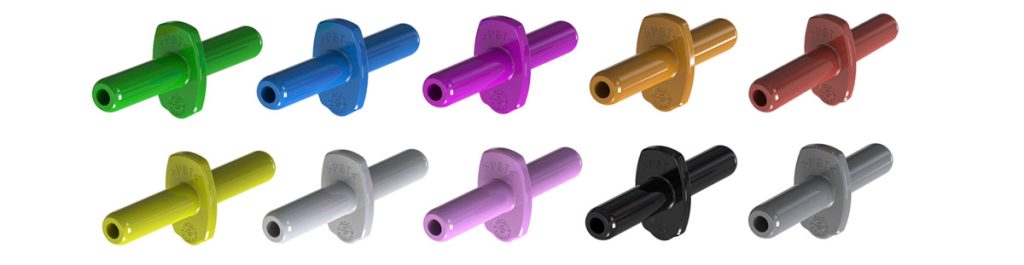
Line Meters are a ‘push-in’ orifice device with a tapered bore. This tapering ensures that the device has no ‘dead spots’ (like a flat orifice plate placed within a chamber). This characteristic enhances linear flow and reduces the chances of crystal build-up that can result in blockages. Line Meters range from 0.70mm to 2.5mm bore.
LINE METER BORE SIZE – Green:0.70 / Blue:0.85 / Purple:1.0 / Orange: 1.1 / Yellow:1.2 / White:1.3 / Pink:1.5 / Black:1.7 / Brown:2.1 /Grey:2.5
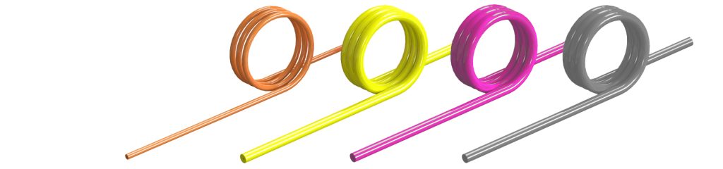
Friction Tube
Fiction Tube – FIBP (Friction Induced Back Pressure) tubing is our other method of restricting flow to create system pressure control. It is particularly useful for applying liquids which are highly viscous or liquid blends that have compatibility issues. Because it has a relatively large bore, particles can easily pass through the tube. It is not as prone to product build-up from elements such as zinc. It is also particularly useful for achieving very low rate application with unbroken streams. Tube is also positioned within the “Terminal Assembly” of the “Stacker Distribution System” and must be located downstream from the 2 psi Check Valves to ensure that the Check Valves can function correctly.
There is a lag time however, associated with this restriction method as liquid in the tube may drain back to the check valve (due to it being located downstream). Three bore sizes are available in FIBP tube, 1.2mm, 1.5mm and 1.8mm. There are three OD’s to facilitate adaptation to differing stainless steel delivery tubing at the openers.
Back pressure for this restrictive method is determined by the product SG (Specific Gravity), application rate and the corresponding length of tube determined by following charts. FIBP Tube is generally not used on Row Crop Planters due to inherently wider row spacing —(higher flow rates per outlet means larger bore line meters are preferable).
TUBE DIMENSIONS – 3.0mm OD X 1.2mm ID (Orange) / 5.0mm OD X 1.2mm ID (Yellow) / 5.0mm OD X 1.5mm ID (Pink) /5.0mm OD X 1.8mm ID (Grey)