QUICK TROUBLESHOOTING GUIDE
Ai Series and LQS Series
| PROBLEM | POSSIBLE CAUSE | RESOLUTION |
| Pump won’t suck | Air in suction line. | Air in the suction lines may prevent the pump from sucking liquid. Air can be vented on the suction side via the suction filter.
1. Undo yellow end cap and unscrew filter bowl. |
| Blocked suction filter | Check and Clean Suction Filter. Refer to Maintenance section in manual for instructions.
It is important that after the suction filter screen has been inspected and cleaned that the screen correctly to the filter body (The valve pin location is crucial to operation of the filter). |
|
| Air Leak on Suction Side of Pump | Check hoses and fittings for splits and correct seating. | |
| Obstruction on Suction Side of Pump | Check all hoses fittings. Check source selector valve is in correct position. Check tank suction outlet valve is open. | |
| Pump Fault | Pump faults that may occur include broken valve springs, debris in valves or damaged diaphragms. Overhaul pump to check valves and diaphragms. | |
| PROBLEM | POSSIBLE CAUSE | RESOLUTION |
| Pump Noisy / Banging | Excessive hydraulic flow from tractor. | The pump is speed protected via a flow control block fitted to the pump’s hydraulic motor. Excessive hydraulic flow from the tractor may trigger its own hydraulic relief system into play causing ‘hammering’. This can be difficult to diagnose as it may appear that the hammering is coming from the pump itself.
Reduce hydraulic flow from the tractor – (a flow of approx. 20-22lpm. should provide sufficient pump speed) |
| PROBLEM | POSSIBLE CAUSE | RESOLUTION |
| Rapid loss of pump oil | Split diaphragm or leaking end seal. | Check to see if oil is leaking around end seal. Check diaphragms for splits. Replace seal or diaphragms as necessary. Refer to Bertolini pump manual for details. |
| PROBLEM | POSSIBLE CAUSE | RESOLUTION |
| No rate control, actual rate too HIGH | Restrictive devices in distribution system are too large.
This will also be indicated by low system pressure. |
Metering system (on tillage bar) restrictive devices too large. – (This causes excessive leakage within the metering system downstream from the servo valve). When this happens (usually when the operator is attempting very low rates), there is insufficient back pressure to stabilise the system. Under these circumstances the servo will attempt to compensate by fully opening back to tank when in reality the liquid has already escaped – consequently, there is no system control.
Fit smaller restrictors in the distribution system. |
| Tank agitation line switched off or too restricted.
(Not applicable for LQS Series) |
Check agitation valve at rear of module. If valve is closed, open it up and retest system with target rates. Check size of nozzle in agitator, install a larger nozzle or remove the nozzle altogether. Different agitator nozzle sizes are available from your dealer. Agitators should be installed to provide agitation at bottom of tank. | |
| Excessive Flow from Pump
(Not applicable for LQS Series) |
If actual rate is still too high, reduce flow from pump. Refer to Manual instructions to CHECK AND ADJUST PUMP SPEED. | |
| PROBLEM | POSSIBLE CAUSE | RESOLUTION |
| No rate control, actual rate too LOW | Restrictive devices in distribution system are too small.
This will also be indicated by high system pressure. |
If the restrictive devices are too small, then the pressure will exceed the PRV setting. The PRV will bypass liquid back to tank and the regulating control valve then becomes ineffective.
Fit larger restrictors in the distribution system. |
| Inadequate restriction on tank agitation line.
(Not applicable for LQS Series) |
Check tank agitator is installed on end of tank agitation line. Install a smaller size agitator nozzle to increase restriction.
Different agitator nozzle sizes are available from your dealer. Agitators should be installed so as to provide agitation at bottom of tank. |
|
| Insufficient Flow from Pump | If actual rate is still too low, increase flow from pump. Refer to Manual instructions to CHECK AND ADJUST PUMP SPEED. | |
| PROBLEM | POSSIBLE CAUSE | RESOLUTION |
| No rate control or wildly fluctuating rates | Servo valve polarity is incorrect. | Check Servo valve polarity – (servo valve opens when it should be closing). Use the Control Valve Test function of the Greenstar™ Rate controller. Pressing the “+” button should close the valve and “-” should open it. |
| Pump not functioning properly. | Pump may not be performing properly. This could be due to suction, discharge, or speed problems. Suction Filter may be blocked or inlet to pump impaired (broken valve spring, debris in valve etc.). Pressure side of pump may be impaired – (broken valve spring, debris in valve etc.). Pump may not be operating at a constant speed due to erratic hydraulic flow from tractor.
Check and Clean Suction Filter / Check hydraulic flow to pump. |
|
| Incorrectly fitted, faulty or damaged speed sensor | Test the speed sensor against the tractor speedometer. | |
| Faulty Flowmeter | Perform repeat flowmeter calibrations. Check for consistency of results | |
| Faulty Servo Valve | Use the Control Valve Test function or manual override in control system to check servo valve is working. | |
| Over-responsive Servo Valve | Adjust responsiveness of servo valve in control system configuration. |
PRODUCT MANUALS
PUMP AND CONTROL MODULES
CLICK HERE to request your Module Manual PDF.
STACKER DISTRIBUTION
AIR TOOL SINGLE SWATH I PLANTER SINGLE SWATH I SECTION CONTROL
VIDEO
More “How to videos” CLICK HERE
Controller Set up Guides
FAST SHUTOFF SYSTEMS
GREENSTAR – Single Product GREENSTAR – Single Product with Section Control
JDRC2000 – Single Product JDRC2000 – Single Product with Section Control
RAVEN RCM – Single Product RAVEN RCM – Single Product with Section Control
TOPCON APOLLO – Single Product TOPCON APOLLO – Single Product with Section Control
VIDEO
TOPCON APOLLO – Single Swath for LQS70 / LQS120 / LQS180 Modules
TOPCON APOLLO – Section Control
TOPCON APOLLO – Single Swath for LQS20 & LQS-SPK Modules
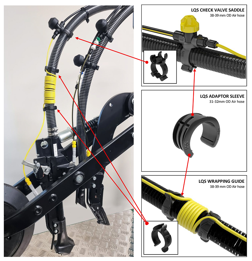
HARNESS GUIDE
FLOW METER IDENTIFICATION
All Liquid Systems (SA) Pump and Rate Control Modules are available with multiple flow meter configurations to suit specific applications and flow rates. Each flow meter has a ‘Calibration Factor’ which needs to be input to the rate controller by the operator. If the incorrect calibration factor is used, the system will not operate correctly, and the applied rate will be incorrect. The below images and tables show the different flow meters and associated calibration factors.
Teejet 801 Flow Meter |
|
| RANGE: | 7.5-250 L/Min |
| Pulses Per litre | 82 |
| Pulses Per US Gallon | 310 |
| Pulses Per Imperial Gallon | 373 |
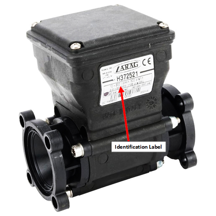
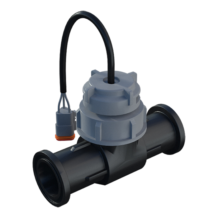
ARAG Electromagnetic Flow MeterARAG Flow Meters all appear visually the same, although can be identified by the label on the side. This label shows the range and calibration factor in pulses per litre. The table below shows all available options. |
|||
| RANGE: | 2.5-50L/Min | 1-20L/Min | 0.5-10L/Min |
| Pulses Per litre | 1200 | 3000 | 6000 |
| Pulses Per US Gallon | 4542 | 11355 | 22710 |
| Pulses Per Imperial Gallon | 5455 | 13638 | 27277 |